Air Valves in HAMMER
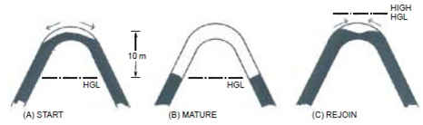
Air valves are installed at local high points along pipelines to allow air to come into the system during periods when the head drops below the pipe elevation and expels air from the system when fluid columns begin to rejoin. The presence of air in the line limits sub-atmospheric pressures in the vicinity of the valve and for some distance to either side, as seen in profiles. Air can also reduce high transient pressures if it is compressed enough to slow the fluid columns prior to impact.
Within HAMMER, both steady (initial) runs are made plus the actual transient simulation. The first part of this help topic address the steady behavior (more details available in WaterGEMS/WaterCAD help. The remainder presents the behavior in a transient simulation.
The theory and numerical methods used in HAMMER's transient analysis are discussed in help topic Air Valve Theory.
Initial Conditions (steady state or EPS)
- The "Treat air valve as junction" property must be set to "false". Note that treating an air valve as a junction only applies to the initial conditions (steady state or EPS); the air valve will always be treated as an air valve during a transient simulation.
- If an air valve becomes open during the initial conditions calculation (steady state or EPS), the hydraulic grade on the downstream side may be less than the pipe elevation. This can be displayed as the hydraulic grade line drawn below the pipe. This should be interpreted as a pressure pipe that is not flowing full. Full flow resumes at the point where the hydraulic grade line crosses back above the pipe.
- Because air valves have the possibility to switch status during a steady state or EPS, they can lead to instability in the model especially if there are many air valves in the system. To improve the stability of the initial conditions, it is desirable to force some of the valves closed. This can be done by setting the property "Treat air valve as junction" to True for those valves that are expected to remain closed.
- If all of the pumps upstream of an air valve are off during a steady state or EPS run, the pressure subnetwork is disconnected in that area and the model will issue warning messages for all nodes in that vicinity indicating that they are disconnected.
- Air valves that are open in the initial conditions will need to have the initial air volume defined for transient analysis purposes. The friction factors in the adjacent pipes may also need to be checked, as the head loss computed by the initial conditions calculation may not be a true head loss. It may be necessary to specify the initial conditions manually (by setting the 'Specify Initial Conditions?' Transient Solver calculation option to True - see the Calculation options topic for details - then manually typing in values for the fields grouped under Transient Initial in the Property Editor.
Given the above challenges, the user should consider terminating the system at the high point, using a reservoir or Discharge To Atmosphere node in place of the air valve. This approach is typically acceptable for a transient simulation because the transient waves would not propagate past the air gap formed at the air valve.
Transient Simulation
During the transient simulation, an air valve will always be treated as an air valve. There are two ways in which an air valve can behave:
- Pressure below atmospheric - the air valve is open and acts to maintain a pressure of zero in the vicinity of the air valve. Air is admitted into the system.
- Pressure above atmospheric - if an air pocket previously accumulated, air will start to expel out of the air valve (unless using a Vacuum Breaker type). Once any air is fully expelled, the air valve is closed and acts as a junction node.
The presence of air in the line limits subatmospheric pressures in the vicinity of the valve and for some distance to either side, as shown on HAMMER profile graphs. Air can also reduce high transient pressures if it is compressed enough to slow the water columns prior to impact.
Note: low or subatmospheric pressure can still occur further along the pipeline; the air valve element only provides local protection.
Typically, the air inlet orifice is large enough so as to allow free air intake and not throttle due to the sonic limit. If the air inflow orifice is too small, the model may show the hydraulic grade dipping below the physical elevation of the air valve (negative pressure) in an animation of the profile. Limiting air outflow using a small orifice will cause the air to compress inside the pipe and cushion the water column collapse.
Without an air valve, subatmospheric pressure (such as those caused by an emergency pump shutdown) can cause contaminants to be sucked into the system, thin-walled pipes can collapse and also vapor pockets can form (as the water boils at such low pressures) and subsequently collapse or damage pump impellers.
However, you must be careful when using the air valve, since extreme high pressure surges can be caused when the air pocket collapses. Meaning, if the air inside the air valve is expelled too quickly, the water columns in the adjacent pipes can collide at a high velocity and the force will cause a severe transient. This is similar to the surge that occurs when a water column slams against a closed valve, except in this case the momentum of two water columns are hitting each other, without the delay involved with valve closure. However, an air outlet orifice that is too small can also cause a problem, if the air cannot escape quickly enough. So, care must be taken to select an appropriate air valve type and size, so as not to cause worse transients than if no valve had been used. It is common to use a "triple-acting" air valve to help against this problem, as this type of air valve throttles the size of the outflow orifice (typically using a float.)
The following HAMMER attributes describe the air valve behavior during a transient simulation. For more on the different types, see Determining the Type of Air Valve to Use.
- Time to Close: For an air valve, adiabatic compression (i.e., gas law exponent = 1.4) is assumed. The valve starts to close linearly with respect to area only when air begins to exit from the pipe. If air subsequently re-enters, then the valve opens fully again. It is possible for liquid to be discharged through this valve for a period after the air has been expelled.
- Diameter (Air Outflow Orifice): Diameter of the air outflow orifice (the orifice through which air is expelled from the pipeline).
- Air Volume (Initial): Volume of air near the valve at the start of the simulation. The default is zero. If volume is nonzero, the pressure must be zero.
- Diameter (Air Inflow Orifice): Diameter of the air inflow orifice (the orifice through which air enters the pipeline when the pipe internal pressure is less than atmospheric pressure). This diameter should be large enough to allow the free entry of air into the pipeline. By default, this diameter is considered infinite (i.e. there is no restriction to air inflow).
- Diameter (Air Outflow Orifice): Diameter of the air outflow orifice (the orifice through which air is expelled from the pipeline). By default, this diameter is considered infinite.
Triple Acting Air Valve Type
- Air Volume (Initial): Volume of air near the valve at the start of the simulation. The default is zero. If volume is nonzero, the pressure must be zero.
- Trigger to Switch Outflow Orifice Size: Select whether the transient solver switches from the large air outflow orifice to the small air outflow orifice based on Transition Volume or Transition Pressure.
- Transition Pressure: The local internal system air pressure at the air valve above which the transient solver switches from using the large air orifice to the small air orifice (in order to minimize transients).
- Transition Volume: The local volume of air at the air valve below which the transient solver switches from using the large air orifice to the small air orifice (in order to minimize transients). This volume often corresponds to the volume of the body of the air valve.
- Diameter (Small Air Outflow Orifice): ): Diameter of the air outflow orifice (the orifice through which air is expelled from the pipeline) when the local air volume is less than the transition volume (TV), or the air pressure is greater than the transition pressure (TP) (depending on which trigger is used to switch the outflow orifice size). This diameter is typically small enough for the injected air to be compressed, which can help prevent severe transient pressures. Generally air flows out the large air outflow orifice for some time before switching to the small air outflow orifice for the final stages of air release.
- Diameter (Large Air Outflow Orifice): Refers to the discharge of air when the local air volume is greater than or equal to the transition volume (TV), or the air pressure is less than or equal to the transition pressure (TP) (depending on which trigger is used to switch the outflow orifice size). This diameter is typically large enough that there is little or no restriction to air outflow. Generally air flows out the large air outflow orifice for some time before switching to the small air outflow orifice for the final stages or air release.
- Diameter (Air Inflow Orifice): Diameter of the air inflow orifice (the orifice through which air enters the pipeline when the pipe internal pressure is less than atmospheric pressure). This diameter should be large enough to allow the free entry of air into the pipeline. By default, this diameter is considered infinite (i.e. there is no restriction to air inflow).
Vacuum Breaker Air Valve Type
Diameter (Air Inflow Orifice): Diameter of the air inflow orifice (the orifice through which air enters the pipeline when the pipe internal pressure is less than atmospheric pressure). This diameter should be large enough to allow the free entry of air into the pipeline. By default, this diameter is considered infinite (i.e. there is no restriction to air inflow.